This week we learned about the mighty microcontrollers and explored some new ones.
Requirements
- Demonstrate and compare the toolchains and development workflows for available embedded architectures
- Document your work to the group work page and reflect on your individual page what you learned.
- Browse through the datasheet for your microcontroller
- Write a program for a microcontroller, and simulate its operation, to interact (with local input &/or output devices) and communicate (with remote wired or wireless connection).
Group Assignment
Individual Assignment
Softwares 💻
- Arduino IDE
- Microsoft| MakeCode
- Wokwi
- Postman
- NASA Horizon API
not a software but can't a girl just flex?
Group Assignment
So microcontrollers! This Week We get to read datasheets and try different microcontrollers. First we discussed the difference between Harvard vs Von Neumann Architecture. Understood the basic Architecture of ESP32‑C3 & ATMega328P via their datasheets. Then went and read some datasheets. I read through these two datasheets. The plan was to browse through esp3-c3's datasheet and use the xiao esp3-c3 but for some reason that didn't work and after 4 hours of trying to make it work I decided to use the esp32 instead. I will explain the issue in the planning phase
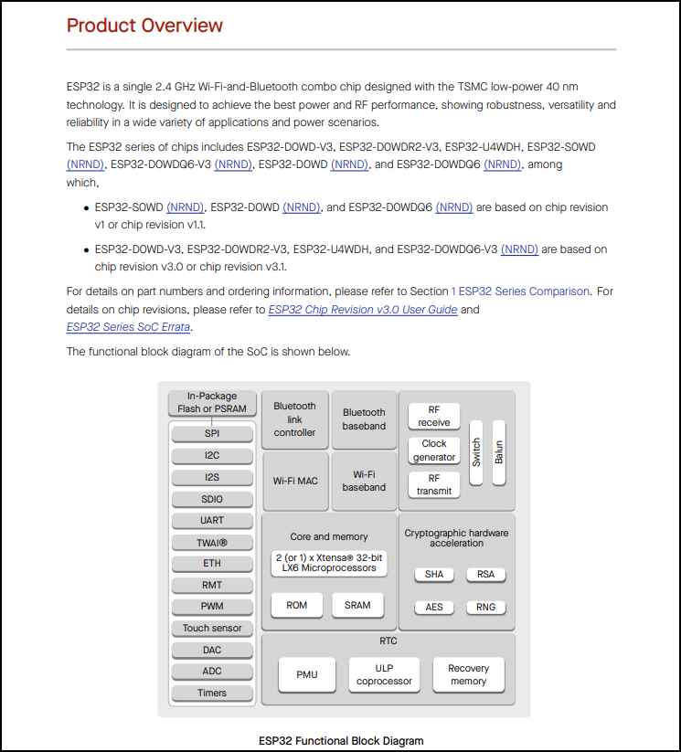
ESP32 datasheet
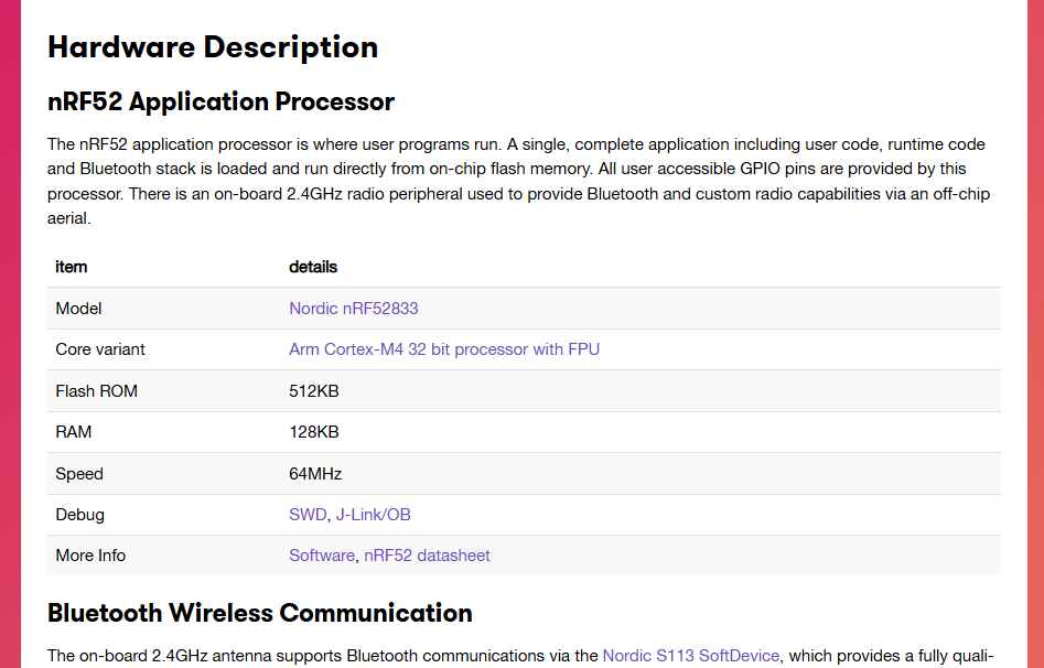
Microbit: It was quite challenging to find the MCU datasheet since the link lead to dead end.
Features
| Specs | Esp32C3 | Micro:bit V2 |
|---|---|---|
| Microcontroller (MCU) | ESP32 | Nordic nRF52833 |
| MCU Produced By | Nordic Semiconductors | Espressif Systems |
| MCU Core(s) | • Xtensa® single-/dual-core 32-bit LX6 microprocessor(s) | Arm Cortex-M4 32 bit processor with FPU |
| MCU Max Frequency | 240 MHz | 64MHz |
| MCU Operating Voltage | 2.2V - 3.6V | 1.8V .. 3.6V |
| Board Clock Frequency | 40 MHZ | 64 MHz from 32 MHz external crystal or internal 32 kHz from crystal, RC or synthesized |
| Board Flash | 4MB | 512 KB |
| Board SRAM | 520KB | 128 KB |
| Board Digital I/O Pins | 34 | 19 |
| Board Analog Out Pins | 2 | 19 may be assigned for up to 3 simultaneous PWM channels |
| Board Analog In Pins | Up to 18 ADC-enabled pins | 6 |
Micro:Bit
The micro:bit is a fun board to play with. It's mainly designed for educational reasons but it's still a very
powerful
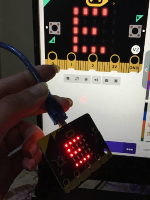
It has a 5x5 LED matrix, 2 buttons, and the tool I played with the compass .
I used the Microsoft's Make Code. MakeCode is a web-based programming environment that allows users to program the micro:bit using either block-based
I used this guide to make a compass. It was super fun and I liked how it calliberated its axes.
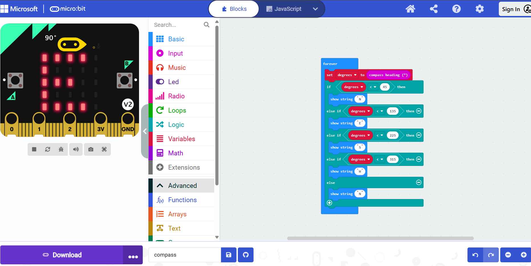
The Compass being a compass
ESP32
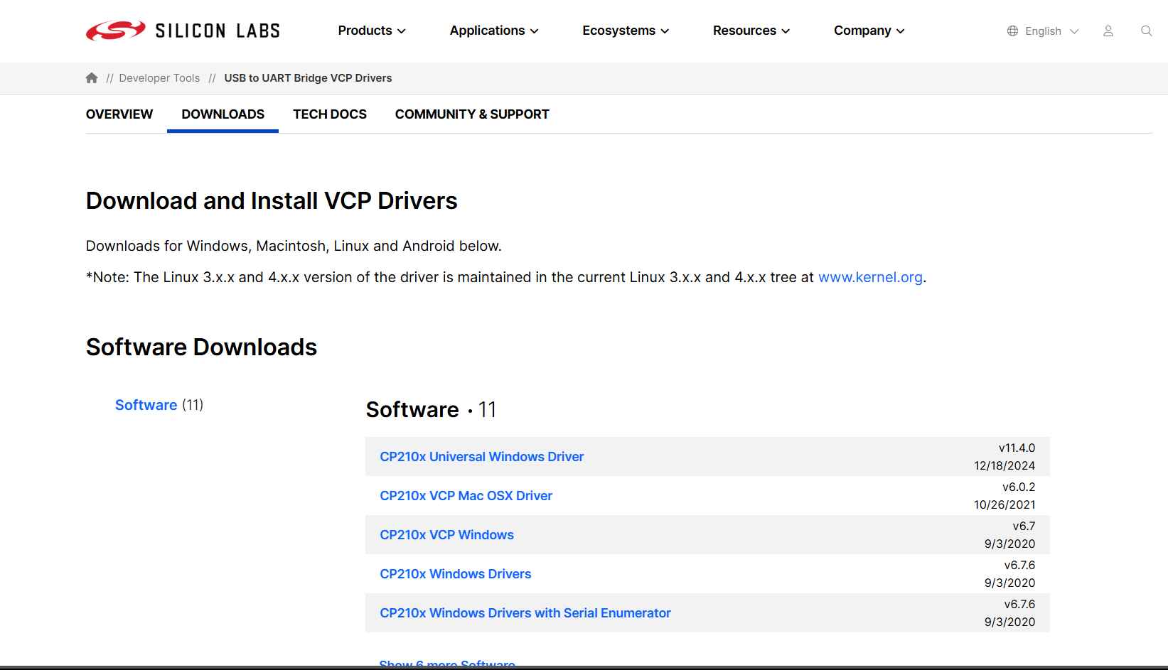
First I downloaded the drivers from here for my laptop to be able to read the port. I already had Arduino IDE so I only added the esp32 library
I used a blinking examples from the library examples of esp32.After I downloaded the drivers and esp32 library in Arduino IDE
Planet Indicator
The Idea
For this week I wanted to make something that might help me for my final project. I'm thinking of making a
smart Orrery
that will show the position of an astronomical object and the sun in real time.
This means I want to explore the map() function with the ESP32 and if I have time try the
Get HTTP request from real time
data using an API. So I decided with to my instructor to use these components.
The Components
| Function | Components |
|---|---|
| Microcontroller (MCU) | ESP32 |
| Input | Potentiometer |
| Output | Servo Motor |
| communications | LCD I2C |
The Plan
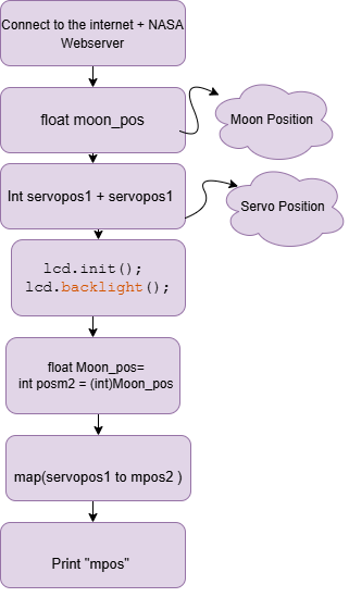
Upon the advise of our instructor, it was best to make a flowchart to understand the logic behind our code. This makes it easier to debug and oversee the whole picture. I used a website called draw.io to make my flowchart. I was planning on using 2 servos but I decided to use only one but the logic still applies. From my flowchart you can see that first I have to make the esp32 connect to the wifi, retrieve the data of the moon position especially a certain parameter called Right Ascension . Right ascension (RA) is the celestial equivalent of longitude. RA can be expressed in degrees, but it is more common to specify it in hours, minutes, and seconds of time: the sky appears to turn 360° in 24 hours, or 15° in one hour. So an hour of RA equals 15° of sky rotation.
Then the data received store it into a variable. map the right ascension value to the servo motor. Then show the angle on the LCD Screen.
Plan B is map the servo to a potentiometer.
Simulation
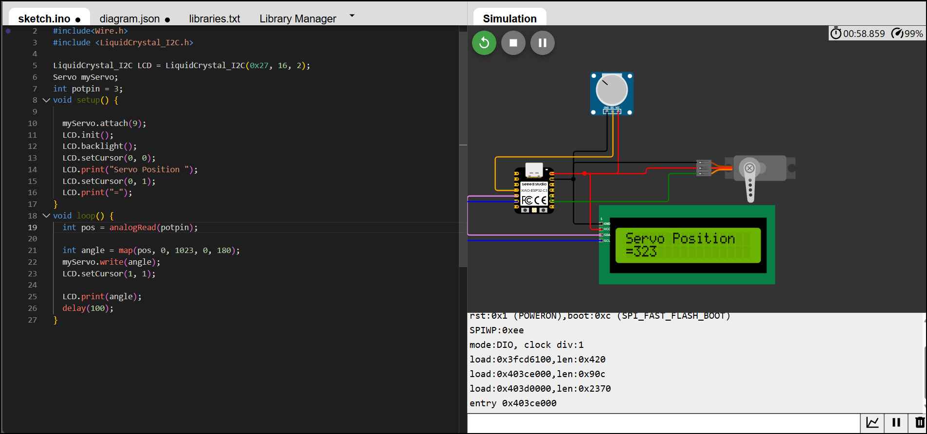
I used wokwi to do my simulation. It's an online simulator taht can simulate ESP32 and Arduino, use different languages like Rust or MicroPython unlike TinkerCAD. it has VS code integration and a lot of libraries. It started pretty good and made a simulation with one potentiometer and a servo using esp3-c3. I wired the potentiometer to D1 Pin and the Servo to D7 Note: in real life D7 is the RX so if you want to use it unplug your servo upload the code then plug it back on. Then added a Junction to both power and GND wires. If you worked with TinkerCAD circuits then wokwi is going to be easy for you.
But I ran into issues with it. for example it lagged a lot and showed this error message
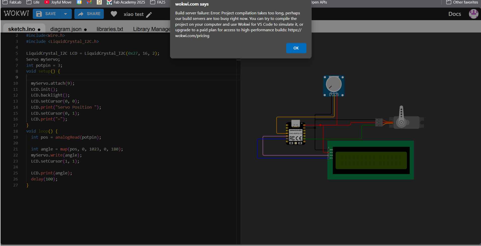
Or something like this
The Issue with Xiao ESP32‑C3
As said initial plans was to uae the xiao esp-c3 but I ran in a recurring error on uploading any code
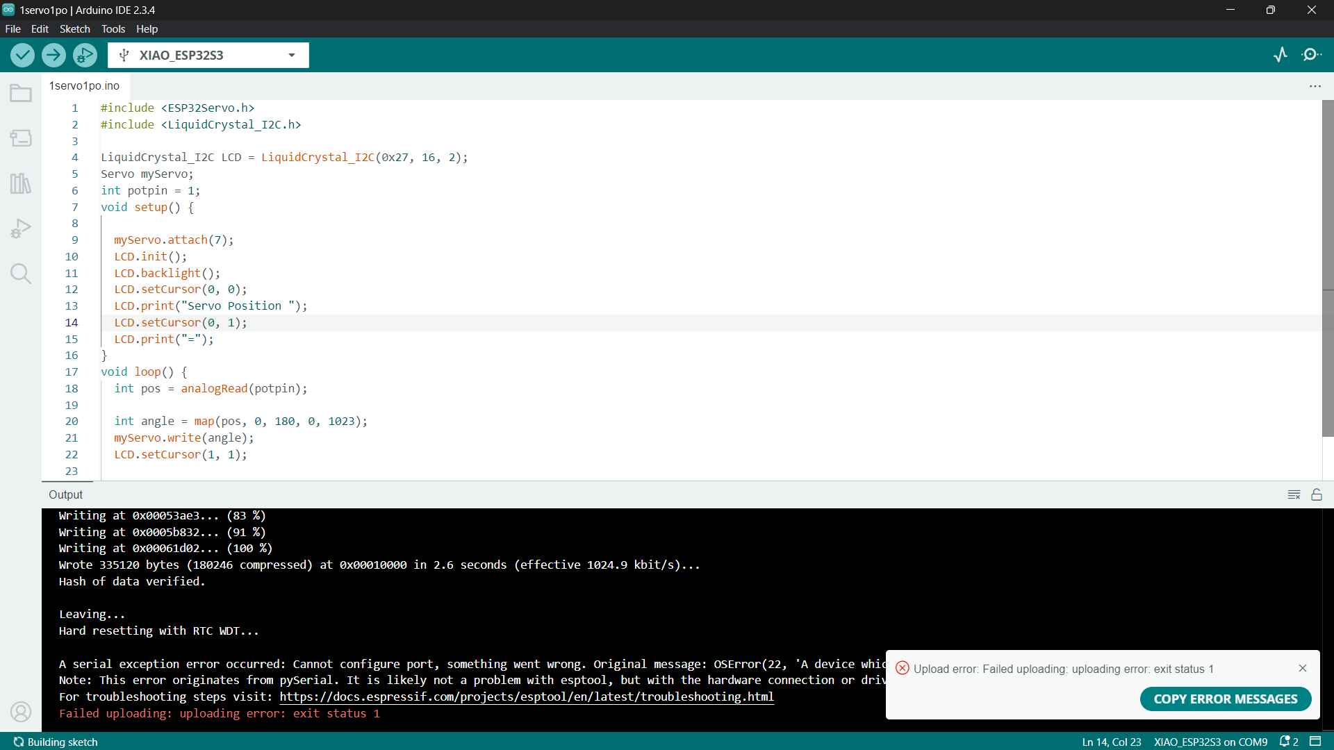
So I used the documentation here And the followed the instruction, re-installed the drivers.Then downloaded the esp test toolsans everything seemed fine it read the com and preformed a reflash the bootloader with factory firmware but once I opened Arduino IDE it would never upload.
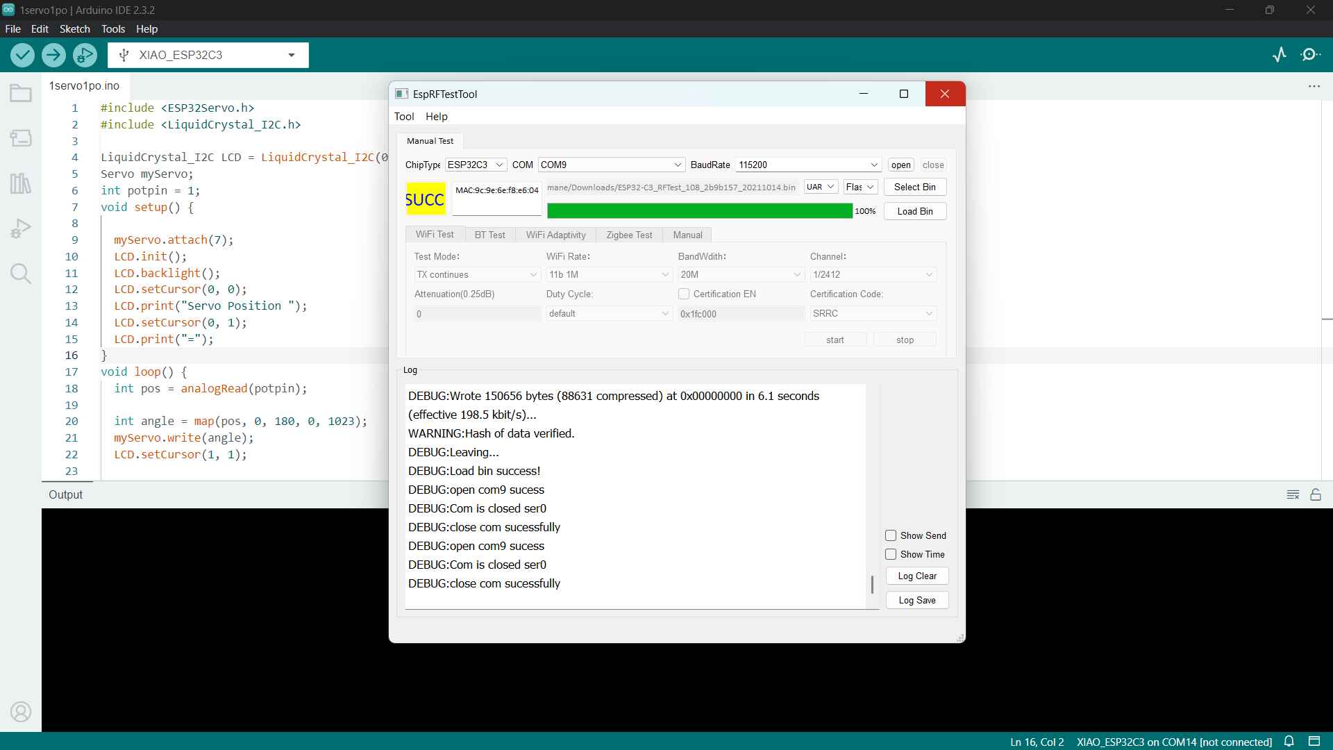
So I used the esp32 for testing the code in real life.
Final Output
The Wiring
-
Step 1
Connected the servo to pin number (18) and the potentiometer to pin number (34).
Connected the LCDI2C SC's SDA(21) to & SCL to (22) since they are commonly used as the default I2C pins.

-
Step 2
I Used a 5V adaptor to power the servo and the LCD I2C while the potentiometer will be power with the Vin.
used a jumper to connect the ground of the adaptor and the GND of the Esp32.
-
Step 3
Upload the code to the ESP32 and test the setup.
The Code
            #include ESP32Servo.h
            #include Wire.h
            #include LiquidCrystal_I2C.h

            LiquidCrystal_I2C LCD = LiquidCrystal_I2C(0x27, 16, 2);
            Servo myServo;
            int potpin = 34;
            int ADC_Max = 4096;
            void setup() {
              LCD.clear();
              LCD.init();
              LCD.backlight();
             LCD.setCursor(0, 0);
              LCD.print("Servo Position ");
              LCD.setCursor(0, 1);
              LCD.print("=");
              myServo.attach(18);

            }
            void loop() {
              int pos = analogRead(potpin);

              int angle = map(pos, 0, ADC_Max, 0, 180);
              myServo.write(angle);
              LCD.setCursor(1, 1);
              LCD.print(angle);
              delay(100);
            }
First we call upon all the libraries we'll need
#include ESP32Servo.h
#include Wire.h
#include LiquidCrystal_I2C.h
Then we initialize the LCD screen and the servo motor. We set the potentiometer pin to 34 and the max value
of the ADC to 4096 in the
LiquidCrystal_I2C LCD = LiquidCrystal_I2C(0x27, 16, 2);
Servo myServo;
int potpin = 34;
int ADC_Max = 4096;
In the Void Setup We set turn on the backlight of the LCD and clear it and print on it thetext "servo
position" and the "=" in the
next line. We tell the esp the servo's signal is connected to pin 18.
void setup() {
LCD.clear();
LCD.init();
LCD.backlight();
LCD.setCursor(0, 0);
LCD.print("Servo Position ");
LCD.setCursor(0, 1);
LCD.print("=");
myServo.attach(18); }
void loop() {
int pos = analogRead(potpin); This line reads the signal of potentiometer and stores it in
the variable pos.
int angle = map(pos, 0, ADC_Max, 0, 180); Here the map function transforms the value of the
potentiometer to the angle of the servo motor.
myServo.write(angle); This is where the servo motor moves to the angle we just mapped.
 LCD.setCursor(1, 1);
                  LCD.print(angle);
                  delay(100);}
Then it prints the angle on the LCD screen in the second row and the second
column.
Getting the API
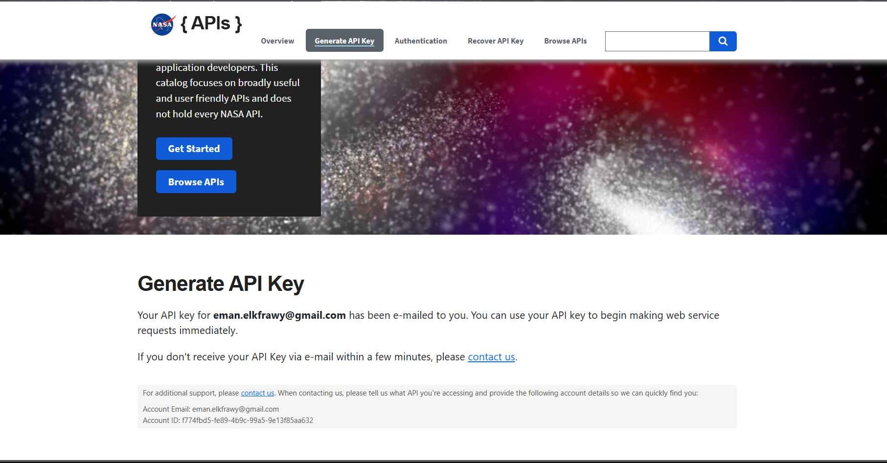
Getting Astronomical data is actually fairly simple since NASA has a dedicated Open API Portal for different types of data ranging from Astronomy Picture of the Day to RAW data of the earth. The first thing i did was creating an API Key with my name and email.
Choosing TheAPI
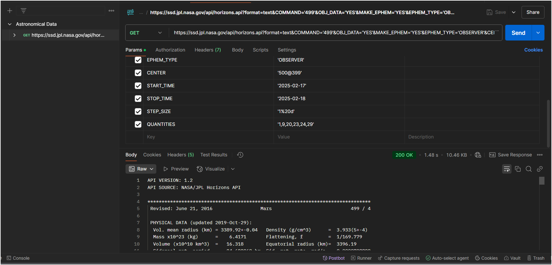
I went with the Horizon API since it has good documentation Then I wanted to know how the data looks like so I understand how to manipulate it. So I followed this youtube tutorial. I went ahead and tried the sample HTTP request in postman for MARS. We can control the data to be in JSON format from the parameter format
How to get the esp to get the data? Fortaunely I found a lot of tutorial doing similar stuff from Random Nerd Tutorials and Last Minute Engineer
I followed the first tutorial to make a sample code that could retrieve the data in the serial monitor
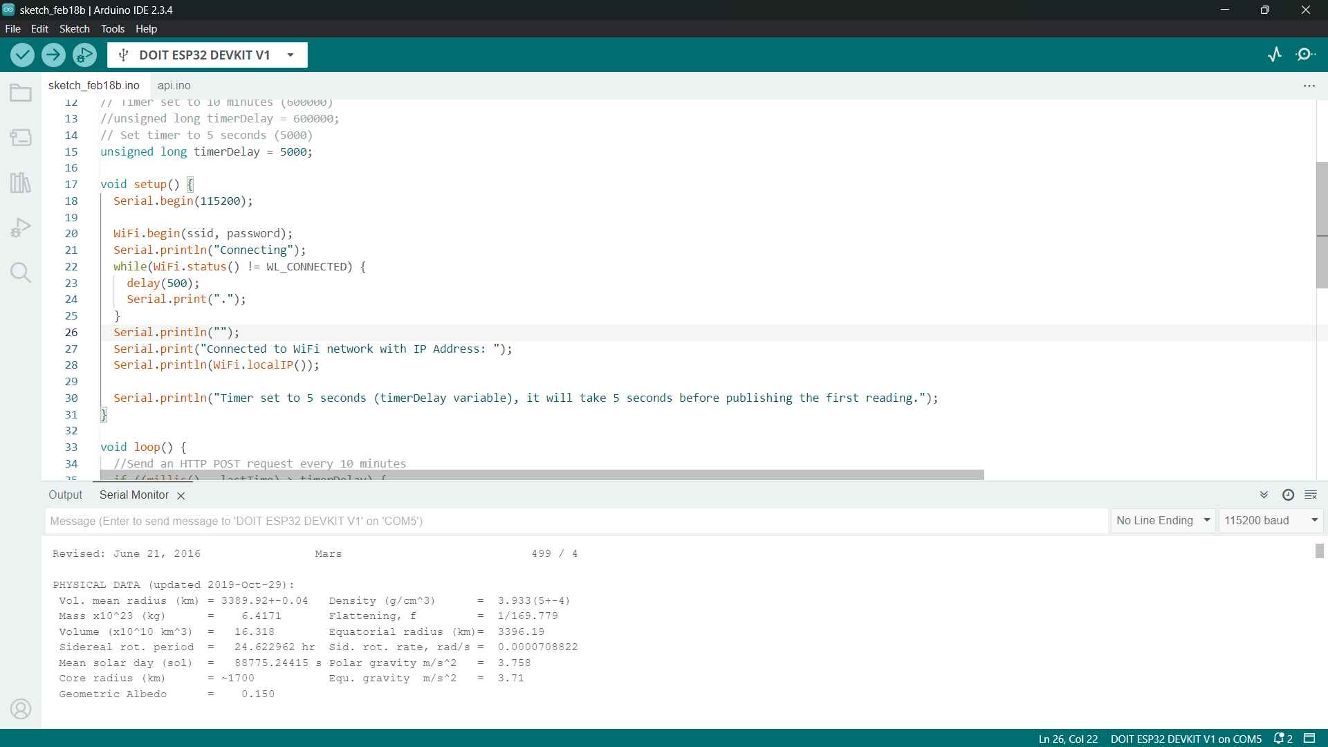
I was planning on using the data to map the servo motor but I ran out of time. I will try to implement it in the final project
The Code
 #include WiFi.h
 #include HTTPClient.h

 const char* ssid = "network";
const char* password = "password";
 const char* HorizonServer = "https://ssd.jpl.nasa.gov/api/horizons.api?format=text&COMMAND='499'&OBJ_DATA='YES'&MAKE_EPHEM='YES'&EPHEM_TYPE='OBSERVER'&CENTER='500@399'&START_TIME='2025-02-17'&STOP_TIME='2025-02-18&STEP_SIZE='1d'&QUANTITIES='*2'";


void setup() {
Serial.begin(115200);

WiFi.begin(ssid, password);
Serial.println("Connecting");
while(WiFi.status() != WL_CONNECTED) {
delay(500);
 Serial.print(".");
}
Serial.println("");
Serial.print("Connected to WiFi network with IP Address: ");
Serial.println(WiFi.localIP());

Serial.println("Timer set to 5 seconds (timerDelay variable), it will take 5 seconds before publishing the first reading.");
                  }

void loop() {

if ((millis() - lastTime) > timerDelay) {
//Check WiFi connection status
if(WiFi.status()== WL_CONNECTED){
 HTTPClient http;

String serverPath = HorizonServer;

 http.begin(serverPath.c_str());
int httpResponseCode = http.GET();

if (httpResponseCode>0) {
Serial.print("HTTP Response code: ");
 Serial.println(httpResponseCode);
 String payload = http.getString();
 Serial.println(payload);
                        }
else {
 Serial.print("Error code: ");
Serial.println(httpResponseCode);
                        }
 http.end();
                      }
else {
 Serial.println("WiFi Disconnected");
                      }
                      lastTime = millis();
                    }
                  }
First we call upon all the libraries we'll need
#include WiFi.h
#include HTTPClient.h
const char* ssid = "network"; put your wifi network
const char* password = "password"; wifi password
const char* HorizonServer = put the http request here in a variable.
In the void setup() initiate the serial and the wifi connection. It will keep trying to connect to the wifi until it does. once connected it'll print ""Connected to WiFi network with IP Address: " and the IP address" In the void loop() we check the connection and retrieve the data. Note we sent a request every 5 seconds
              void setup() {
                Serial.begin(115200);

                WiFi.begin(ssid, password);
                Serial.println("Connecting");
                while(WiFi.status() != WL_CONNECTED) {
                  delay(500);
                  Serial.print(".");
                }
                Serial.println("");
                Serial.print("Connected to WiFi network with IP Address: ");
                Serial.println(WiFi.localIP());

                Serial.println("Timer set to 5 seconds (timerDelay variable), it will take 5 seconds before publishing the first reading.");

                void loop() {

                  if ((millis() - lastTime) > timerDelay) {
                    //Check WiFi connection status
                    if(WiFi.status()== WL_CONNECTED){
                      HTTPClient http;

                     String serverPath = HorizonServer;

                      // Your Domain name with URL path or IP address with path
                      http.begin(serverPath.c_str());


                      int httpResponseCode = http.GET();

                      if (httpResponseCode>0) {
                        Serial.print("HTTP Response code: ");
                        Serial.println(httpResponseCode);
                        String payload = http.getString();
                        Serial.println(payload);
                      }
                      else {
                        Serial.print("Error code: ");
                        Serial.println(httpResponseCode);
                      }
                      http.end();
                    }
                    else {
                      Serial.println("WiFi Disconnected");
                    }
                    lastTime = millis();
                  }
                }
              }